In the previous article, we explored the types and principles of ionization devices that convert samples into ion forms suitable for mass spectrometry. In this article, we will introduce the types of mass analyzers that the sample passes through after the ionization device and their principles.
Before comparing the various types of mass analyzers, it is necessary to understand the difference between the meanings of ‘precision’ and ‘accuracy’ in analysis. In mass spectrometry, precision is related to resolution. If the resolution of a microscope is defined based on the distance between two objects, the resolution in mass spectrometry is defined based on the distance between several peaks appearing in the mass spectrum. The resolution in mass spectrometry is expressed as m/Δm, where m is the mass corresponding to the peak, and Δm is the mass difference between two peaks. Simply put, mass precision (resolution) can be seen as a measure of the ability to separate and analyze two ions with very similar masses. On the other hand, mass accuracy is related to the determination of the ion’s characteristics and indicates how similar the measured mass from MS is to the theoretical mass of the sample. With this concept in mind, let’s look at the types of mass spectrometers.
The currently used types of mass spectrometers are classified into five types, and they can be divided into beam analyzers and trapping analyzers based on their analytical principles. Beam analyzers include three of the five types of mass spectrometers. In these analyzers, the sample ions travel from the ionization device along a beam, pass through the analyzing field, and reach the detector where the analysis is performed.
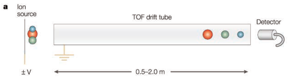
Time-of-flight (TOF)
In a Time-of-Flight (TOF) mass spectrometer, sample ions are simultaneously launched from the ionization device and injected into the TOF drift tube at a constant pressure. At this time, ions with the same charge acquire the same kinetic energy, and ions with lower m/z values move towards the detector at a faster speed. After each ion is accelerated, it flies a fixed distance (0.5-2.0 meters) in the TOF drift tube to reach the detector, and by measuring the time it takes to reach the detector, the m/z value can be calculated.
TOF has a disadvantage in that it is not easily compatible with conventional ionization methods that generate ions continuously, due to the pulsed pattern of ion injection. However, with the advent of pulsed ionization devices such as MALDI, TOF has recently begun to resurge in popularity and is now widely used in conjunction with MALDI. TOF has the advantage of having no theoretical limit on the mass it can analyze, allowing for the analysis of samples with m/z values in the hundreds of thousands.
More precise than linear TOF, advanced TOF analyzers include an ion reflector, where ions are reflected by an electrostatic mirror (reflectron) before reaching the detector. The role of the ion reflector is to correct the slight velocity differences among ions with the same m/z values, compensating for speed variations caused by various factors, thereby increasing the resolution of the TOF.
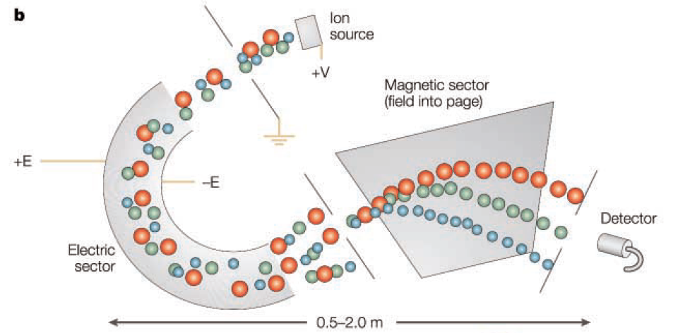
Sector
Every sector includes a magnetic sector, and some also incorporate an electric sector. Ions travel along a curved path in the magnetic sector, maintaining a constant radius relative to the center of the magnetic field. By fixing the magnetic field strength and acceleration voltage, only ions with specific m/z values can pass through a slit. The magnetic sector disperses these ions according to their momentum, acting like a prism. Ions with the same momentum are dispersed at unique angles, passing through the slit in a process called direction focusing. The mass spectrum is obtained by scanning the magnetic field strength that allows ions with different m/z values to pass through two slits, and the resolution is determined by the speed differences of the ions.
To enhance the performance of the sector analyzer, electric sectors can be placed before and after the magnetic sector. The electric sector disperses ions based on their kinetic energy and charge ratio. Although all ions theoretically have the same kinetic energy and follow the same path in the electric sector (thus not allowing mass analysis like the magnetic sector), it induces convergence in the same direction. However, slight speed differences of ions entering the electric sector cause minor dispersion. Using a double sector device, the kinetic energy dispersion in the electric sector can be corrected by the acceleration dispersion in the magnetic sector. Therefore, double sector devices achieve both velocity focusing and direction focusing, overcoming directional and speed differences so that ions with the same m/z value converge at the same point.
Utilizing double sectors, the mass resolution can reach thousands to tens of thousands, and with top-tier instruments, it can exceed a hundred thousand, achieving mass resolutions in the low ppm range.
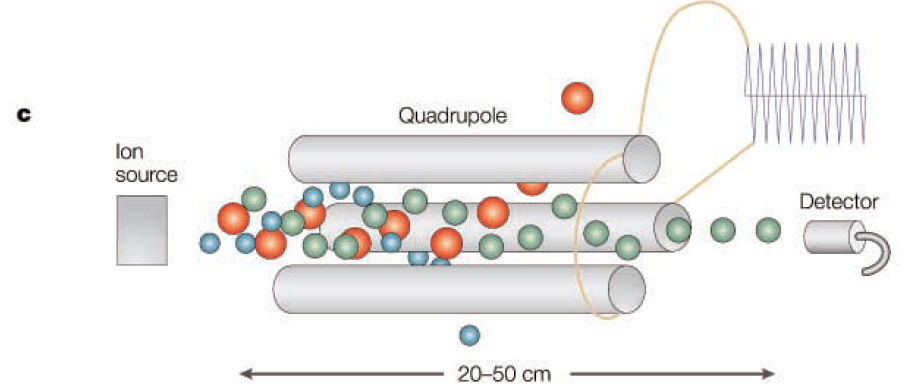
Quadrupole
The quadrupole is the most widely used type of mass analyzer and is often used in conjunction with GC and LC. It accelerates ions with a low voltage and has the advantage of being smaller in size compared to TOF or sector instruments. Ions are separated based on their m/z values through ion motion influenced by a radio frequency within the dynamic electric field of the quadrupole. While the kinetic energy of the ions is a significant variable in TOF and sector instruments, it does not play a major role in the quadrupole.
In this device, mass analysis is performed through direct current (DC) voltage and radio frequency (RF) voltage applied across four cylindrical electrodes. The mass is derived from the relationship between ion motion induced by the time-varying RF and time. This calculation method is much simpler than that used in TOF or sector instruments. The Mathieu stability diagram, a representation used in quadrupole analysis, intuitively shows which ions pass through the quadrupole to the detector and which do not. This graph takes RF voltage and DC voltage as variables, and other variables can include the physical size of the quadrupole, the frequency of the RF, and the m/z values of the target ions.
Typically, the size of the quadrupole and the frequency of the RF are kept constant, and by increasing the RF and DC voltages (while maintaining a constant ratio between them), ions with various m/z values sequentially reach the detector for analysis. Depending on the size of the quadrupole, the maximum m/z value that can be analyzed ranges from 300 to 4000. The mass accuracy is in the range of several hundred ppm, and the mass resolution depends on the RF and DC voltages, with the entire mass range representing unit resolution. However, it should be noted that in most instruments, as resolution increases, sensitivity tends to decrease, which may affect the analysis of ions with high m/z values.
Unlike the beam analyzers mentioned above, trapping analyzers refer to mass spectrometers where ions are not in flight but are instead trapped within the analyzing field for the analysis. The following two types of mass analyzers fall into this category.
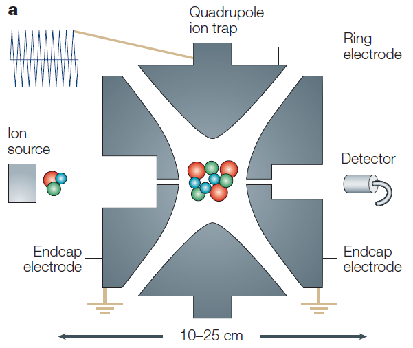
Quadrupole ion trap
The quadrupole ion trap mass analyzer operates on a similar principle to the quadrupole mass analyzer, but with a key difference: ions are trapped in an electric field rather than being in flight. While the quadrupole analyzer has a 2-dimensional electric field (x, y axes) with ions flowing along the vertical (z axis), the ion trap features a 3-dimensional electric field where ions are trapped. The stability diagram in an ion trap works in the same way as in a quadrupole, analyzing and recording the trapped ions. However, the most significant difference is that ions in a quadrupole analyzer have a stable trajectory through the device, whereas in a quadrupole ion trap, the ions have an unstable trajectory from which the mass spectrum is obtained. To destabilize the ions, the rf or dc voltage is increased, allowing for the selection of ions of specific masses for analysis. This ability to select specific masses for analysis is a major advantage of the quadrupole ion trap.
In general, the range of m/z values and resolution achievable with an ion trap are similar to those of a quadrupole. However, the resolution can be greatly improved by setting the rf/dc ratio to a slower pace, increasing the mass range up to 70,000. Moreover, the sensitivity does not significantly decrease at higher m/z values, and mass accuracy is maintained at a similar level. Due to its sensitivity, throughput, ease of operation, and low cost, the quadrupole ion trap is widely used.
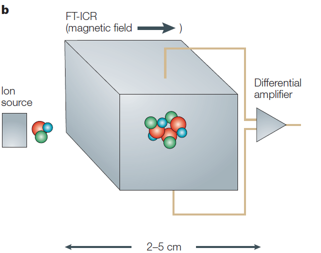
Fourier-transform ion-cyclotron resonance (FT-ICR)
The Fourier-transform mass spectrometer (FTMS), also known as FT-ICR, operates on a principle similar to that of sector instruments, utilizing magnetic fields to determine the m/z values of ions. However, the most significant difference from magnetic sector instruments is the kinetic energy of the ions. While ions in a magnetic sector have kinetic energies in the keV range, ions in an FT-ICR have much lower kinetic energies in the eV range. These lower-energy ions do not pass through the magnetic field but are instead trapped and oscillate at a cyclotron frequency that is dependent on their m/z values within a constant magnetic field. By precisely measuring the oscillation frequencies of the ions, the m/z values can be determined and used for mass analysis. This results in very high mass resolution, which is a significant advantage of FT-ICR. Not only is the mass resolution exceptionally high, but the mass accuracy is also extremely precise, often below ppm levels. However, these benefits come with drawbacks: the equipment is very large, expensive, and has a relatively low throughput compared to other devices, making it less user-friendly than the quadrupole ion trap.
Up to this point, we have introduced five types of mass spectrometers, divided into two main operating principles. In the next article, we will discuss analytical methods that use serially connected MS and the devices used in these methods.
Reference: Glish, G., Vachet, R. The basics of mass spectrometry in the twenty-first century. Nat Rev Drug Discov 2, 140–150 (2003). https://doi.org/10.1038/nrd1011